The microelectronics industry is rapidly migrating to fabricating 3-D wafer stacking interconnects using through-silicon via (TSV) technology. Major market segments seeking to benefit from TSV technology include advanced packaging for memory/logic, light-emitting diodes (LEDs), and compound semiconductor (III-V) high-power radio-frequency (RF) devices. In this cutting-edge technology, fragile device substrates are bonded to carrier substrates with polymeric bonding materials for uniform support during backgrinding (thinning) processes. Device wafers containing various topographies, including etched topographies, high-aspect-ratio structures, trenches, and bored holes throughout the active component area, are first coated and planarized using spin-on bonding materials. Each coated device wafer is then mounted to a rigid carrier and thinned, usually to a thickness of less than100 µm, for further processing. The bonded pair, including the bonding material layer, will be subjected to a wide variety of thermo-mechanical stresses generated during backside processing to thin the device wafer and create electrical input/output redistribution layers (Figures 1 through 5). An effective temporary wafer bonding solution is expected to provide complete support, retain bond strength, and remain soluble for relatively low-temperature (>150°C) separation and cleaning. Temporary bonding process steps include the following:
- Coating the bonding material on device surfaces
- Baking the bonding material layer (by baking at temperatures of ≤180°C)
- Thermo-compressive bonding (at temperatures of ≤180°C)
- Mechanical and chemical backgrinding
- Post-thinning polishing to mitigate micro-crack propagation (also called stress relief etching)
- Photolithography (including baking at temperatures of ≤180°C)
- Plasma etching/reactive ion etching (RIE)
- Resist stripping
- Dielectric deposition (150°-220°C SiO2process)
- Seed layer deposition (by sputtering 220°C copper)
- Electroplating (nickel)
- Thermal debonding (at temperatures of 150°-190°C)
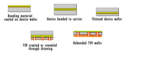
During these process steps, the bonding material must remain adhered and provide sufficient support to the entire thinned device. To obtain consistently high process yields and throughputs, all upstream and downstream processes must be precisely controlled, often by very specialized equipment and tooling to achieve accurate and repeatable results. Coefficient of thermal expansion (CTE) mismatch poses a considerable threat to process integrity by inducing thermal stress. Using device and carrier materials with matching CTEs should be strongly considered. When the carrier and device CTEs cannot be matched, selecting materials with the closest possible CTEs will reduce risks associated with thermal stresses. Additionally, the carrier wafer retains greater structural integrity and will dominate the wafer bow effect. The thermoplastic bonding material layer provides a degree of compliance to relax this internal stress, and thicker bond lines (50-100 µm) work to amplify this effect.
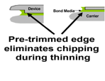
Edge-trimming device wafers and/or using oversized carriers provides loading alignment tolerance and lessens the potential for knife-edge creation along the wafer’s edge, which creates a non-uniform radius and is the main source of chipping and subsequent crack propagation. Many issues related to this type of yield loss can be averted by using edge-prep techniques to replace the rounded edge with a straight wall. Removing 0.5-1.0 mm of the total diameter [of the device wafer?], depending on the overall wafer substrate size, is recommended.
Brewer Science bonding materials are spin applied and require a precision spin coater with environmental chamber controls. Because of the relatively high viscosity of the bonding materials, standard (dip tube) pneumatic dispenses are not recommended for medium-volume, prototyping environments. Gravity-fed pneumatic reservoirs are viable for R&D and low-volume laboratory settings; however, manually pouring and/or transferring the material can result in the infusion of air, which creates microbubbles, and will detrimentally affect suck-back control. Thick-film bonding materials require significantly higher pressures to achieve nominal flow rates, and the overall pressure is directly proportional to the amount of gas dissolution. Recommended flow rates are >1 ml/s. Although bonding material volume will depend on the desired coating thickness, a good rule of thumb is to start with a minimum of 1.5 ml of bonding material per every 100 cm2 of coated surface area.
The ideal equipment for material delivery is a positive displacement pump system. These pumps have the significant advantage of not exposing the material to pressurized gas during fill, dispense, suck-back, and refill sequences. The pumps utilize stepper-motor-controlled diaphragms and provide optimal shot size, dispense rate, suck-back and refill accuracy. One top-of-the-line option, the Cybor 610 pump, provides a specialized recirculation feature to assist in outgassing during the initial purging operation. A reservoir system especially suited for high-viscosity materials is another beneficial accessory to mitigate the introduction of air bubbles during bottle-changing procedures. The system is installed upstream from a high-viscosity pump and features a capacitive sensor that monitors the liquid level and will auto-fill before air can reach the pump source line.
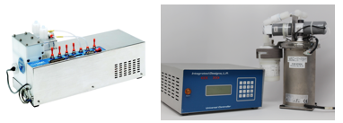
Cybor 610 and 5000 positive displacement pumps


Subscribe to Our Blog