
In addition to precisely controlling application of the materials that enable wafer bonding, a solvent-enriched sealed spin chamber contributes to process integrity. One of the most critical variables in achieving optimal uniformities at the desired target thickness is airflow dynamics. Ideal conditions are created in a sealed chamber with a prewet solvent nozzle, a backside rinse, a lid gasket, a splash ring (air-flow baffle), a programmable exhaust, and center-stream bonding material delivery. Radial and reverse-radial scanning dispense arms are not recommended because they require open bowl environments. Additionally, the scanning technique has not demonstrated significant advantages related to uniformity or material conservation.
A sealed bowl chamber (see bowl image below) improves material consumption, casting characteristics, and coating uniformity. A closed bowl environment combined with a programmable exhaust module allows the solvent vapor concentration to be precisely controlled at various stages in the spin-coating recipe.
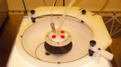
Closed lid with programmable exhaust
Prewet dispense techniques deliver nominal amounts of base-solvent at the onset of depositing the bonding material. This dispense step serves the dual purpose of preparing the surface and increasing the initial bowl vapor concentration. Generally, exhaust is set at 0% (see solvent-enriched environment figure below) during the dynamic dispense and casting portions of the spin recipe. Exhaust flow is typically throttled to 50-100% (see open exhaust environment figure below) during the subsequent drying steps for adequate vapor removal.
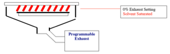
Solvent-enriched environment
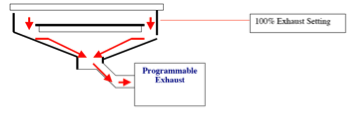
Open exhaust environment
The lid gasket and splash rings seal the chamber and shape the exhaust flow for ideal edge coating. The gasket and rings also mitigate the risk of materials contacting the straight sidewall and redepositing on the upper device area of the substrate.
The backside rinse also helps prevent potential downstream bake plate, bonder, and debonder platen contamination by removing any residual bonding materials that collect on the rear side of the coated substrate.
Proper baking control is essential to achieve void-free media layers and overall high process yields for thick films. After the spin-coating/drying procedure, residual solvent will remain in the bonding material layer. Multistage bake cycles regulate the solvent evaporation rate and mitigate the risk of a “skinning effect.” Skinning results when the outer, exposed layers dry at a faster rate than lower, interior layers. Once skin forms, evaporating solvent below that skin can form blisters in the coating. This phenomenon can be observed if the film is not baked at multiple setpoints (120º-180ºC) and/or is too aggressively ramped to the respective baking temperatures.
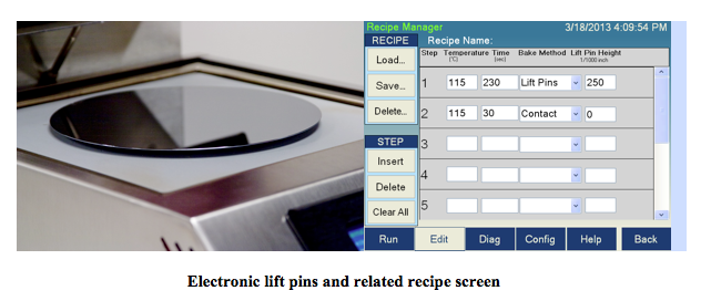
During the backside processes (previously depicted in Part 1 figures) and in the thermal debonding process, failure to properly drive off residual vapors can also lead to vapor flash, greatly increasing the risk of device cracking. The use of two high-uniformity bake plates, featuring pneumatically controlled lift pins to permit proximity bake, soft contact bake, and hard contact bake methods (depicted in the figure below), are recommended for optimal curing results. Utilizing an initial proximity bake method with a nitrogen (N2) pillow lowers the risk of the substrate physically contacting the bake plate and receiving a thermal shock. The slower heating ramp also reduces the risk of blistering and cracking the outer, exposed film surface.
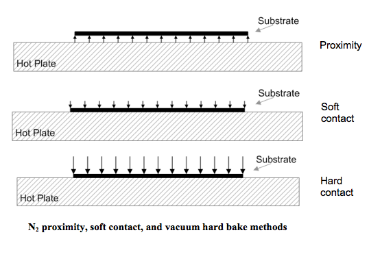
N2 proximity, soft contact, and vacuum hard bake methods
A higher level of precision can be attained by using electronically controlled programmable lift pins. The electronic lift pins provide the user with specific proximity heights above the surface in any sequence or combination. In Brewer Science® Cee® bake plates, the heights are programmed in 0.001-inch increments, with an overall operating window from 0.001 inch through 0.750 inch (± 0.002 inch). This feature allows for more controlled temperature ramping and can emulate several bake plate temperatures with a single bake plate. This feature is also extremely valuable for safely handling thermomechanically sensitive materials, such as GaAs, InP, GaN, SiC, and sapphire substrates, because it reduces thermal shock.
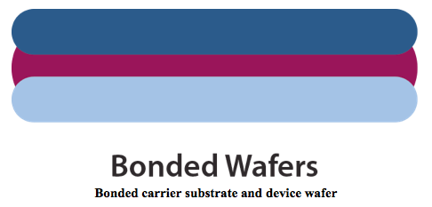
Thermocompressive bonding is often either overlooked or underestimated as a trivial step in the process flow. Precisely controlling process temperatures, achieving platen co-planarity, and maintaining the physical proximity gap between carrier and device during full evacuation (<5 mTorr) prior to physically joining the two substrates (see image below) are all critically important for successful thermocompressive bonding. Failure to control these parameters can lead to trapped pockets of air and solvent, which create voids. Scanning acoustic microscopes can reveal the existence and magnitude of such voids. These voids represent areas of non-uniform support during post-bonding backgrinding and could potentially cause adherence failure during backside processing and debonding processes. Close attention to the recipe parameters and carrier/device orientation is required to achieve a viable material bond line between wafers.
Loading the bonding material–coated device in the lower stack position with the uncoated carrier immediately above is highly recommended. This loading position will reduce the risk of the bonding material making physical contact with the proximity separation pins during evacuation. Such contact could cause subsequent contamination of the next stack and also require excessive cleaning of the equipment.
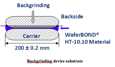
Post-bonding thinning to thicknesses less than 100 µm requires the utmost in precision controls and programmability. Qualified vendors such as DISCO Corporation and Okamoto Corporation should perform this portion of the rough backside grinding process. Following the mechanical rough grinding procedure, post-thinning polishing is recommended to eliminate process-induced subsurface microcracks. SEM images clearly illustrate the presence of countless cleave planes resulting in non-uniform surface stress and warpage. A subsequent mechanical ultrafine grinding or chemical etching process can be used to remove this stress prior to additional thermomechanical processes.

Subscribe to Our Blog